Beam Deflection Formulas
Quick reference for six common idealised beam cases. Use the calculator below for point or uniformly distributed loads, then confirm that its supports and loading match your member.
Beam Deflection Calculator
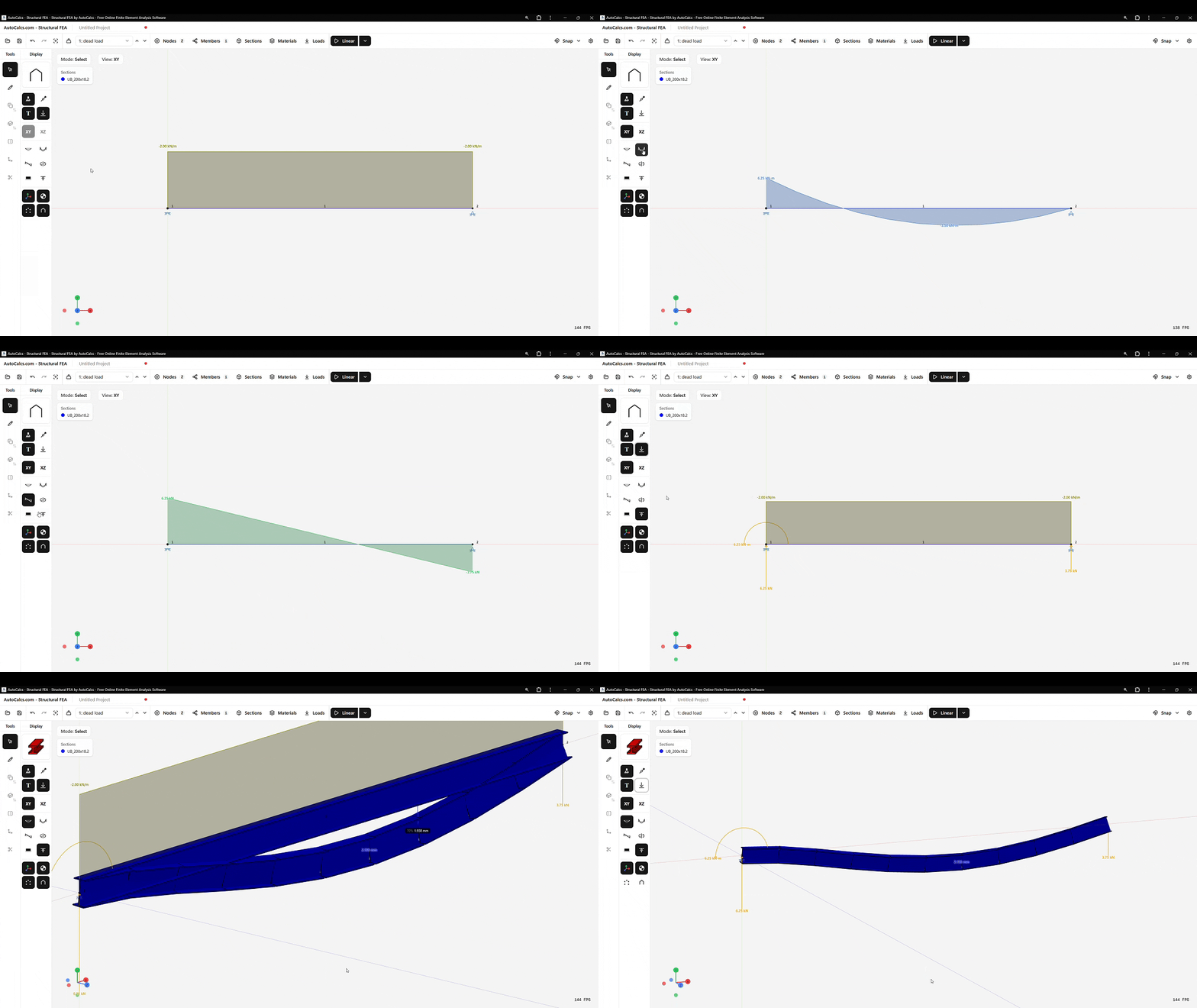
Understanding Beam Deflection
When a beam is loaded, it bends and deflects from its original position. The amount of deflection depends on four factors:
- Load magnitude - More load means more deflection
- Span length - Deflection increases dramatically with span (to the 3rd or 4th power)
- Material stiffness (E) - Higher modulus means less deflection
- Section stiffness (I) - Higher moment of inertia means less deflection
The product EI is called the flexural rigidity and appears in the denominator of all deflection formulas. To reduce deflection, you can increase E (use a stiffer material) or increase I (use a deeper or wider section).
Simply Supported Beam Formulas
Uniformly Distributed Load (UDL)
Maximum deflection occurs at midspan. This is the most common case for floor beams supporting uniform floor loads. The coefficient 5/384 ≈ 0.013.
Point Load at Center
Maximum deflection occurs at midspan under the load. The coefficient 1/48 ≈ 0.021 is larger than the UDL coefficient-a concentrated load causes more deflection than the same total load distributed uniformly.
Point Load at Any Position
δmax = Pb(L² − b²)3/2 / (9√3 · EIL) (true maximum, when a > b)
located at x = √((L² − b²) / 3) from the support farther from the load
where a + b = L, with a measured from the left support
When the load is not at midspan, the deflection at the load point is Pa²b²/(3EIL), and the true maximum sits slightly toward the longer span. The maximum-deflection formula uses the shorter distance b in the numerator (Roark Table 8.1, Hibbeler Appendix C). For loads near midspan the two values are nearly identical.
Cantilever Beam Formulas
UDL Along Full Length
Maximum deflection occurs at the free end. The coefficient 1/8 = 0.125 is much larger than the simply supported UDL coefficient; the ideal cantilever deflects about 10 times more for the same load intensity, span, and EI.
Point Load at Free End
Maximum deflection at the free end under the load. The coefficient 1/3 ≈ 0.333 shows why cantilevers need careful deflection checks.
Fixed-End Beam Formulas
UDL Along Full Length
Maximum deflection occurs at midspan. The coefficient 1/384 ≈ 0.0026 is five times smaller than the simply supported UDL coefficient; ideal fixed ends substantially reduce deflection.
Point Load at Center
Maximum deflection at midspan. The coefficient 1/192 ≈ 0.0052 is 4× smaller than the simply supported case.
Deflection Limits
Building codes and project criteria limit deflection to control finishes, ponding, alignment, vibration perception, and other serviceability effects. Common reference ratios include:
- L/180 and L/240 for some roof or total-load checks
- L/360 for many floor or finish-sensitive checks
- L/500 and tighter where project-specific performance requires it
These are examples, not universal limits. The governing ratio, span definition, and whether to use live, snow, wind, total, or incremental deflection depend on the applicable code and supported construction. Camber does not remove the need to check the required deflection components.
Units and Consistency
The formulas work with any consistent unit system. Common combinations:
| System | Span (L) | Material (E) | Section (I) | Result (δ) |
|---|---|---|---|---|
| Metric (mm) | mm | MPa | mm⁴ | mm |
| Imperial (in) | in | ksi | in⁴ | in |
Related Calculators
Section Properties
Area, inertia, section modulus, and torsion constant
Moment of Inertia
Second moment of area for common shapes
Preliminary Beam Load
Preliminary load limit from bending and deflection screens
Unit Converter
Convert force, stress, mass, and more
Young's Modulus
Calculate E from stress-strain data
K-Factor (Effective Length)
Column effective length from alignment chart
Embodied Carbon
Estimate A1–A3 kgCO₂e from member masses and emission factors
Steel Weight
Estimate steel mass from unit mass, length, and quantity
Von Mises Stress
Equivalent von Mises stress from 3D or plane stress states
Principal Stress & Mohr's Circle
Principal stresses, max shear, and orientation from a 2D state
Plate Deflection & Stress
Flat plate bending stress and deflection under pressure