Verification Model
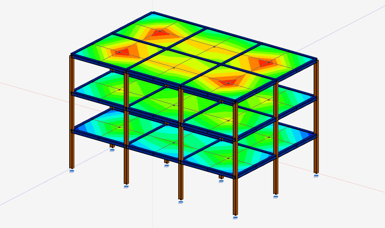
A three-storey frame and shell-slab model compared between AutoCalcs and a separate OpenSees ASDShellQ4 reference model for Linear, P-Delta, and Modal analyses.
The slab mesh and frame members share nodes along the beam lines, so the comparison is focused on frame stiffness, shell stiffness, applied loading, modal mass, and geometric-stiffness behaviour rather than beam-to-shell coupling assumptions.
Model Definition
3 x 2 bay plan, three elevated slab levels, fixed bases, steel frame members, concrete shell slabs, 20 kPa slab pressure, and lateral floor loads of 40, 80, and 120 kN. The model was run in AutoCalcs and compared with a separate OpenSees ASDShellQ4 reference model for Linear, P-Delta, and Modal analyses.
Plate result note: the numeric plate comparison below uses raw element resultants from AutoCalcs and the ASDShellQ4 OpenSees reference run. The browser app defaults to smoothed plate contours for display and reporting because smoothing gives a more usable engineering contour field across a mesh. Smoothing is post-processing, so it is not used as the comparison value here.
Concrete slabs are modelled as linear-elastic shell elements for solver verification. The reported slab deformations are FEA displacement results, not code-based reinforced-concrete serviceability deflection checks with cracking, creep, shrinkage, or long-term modifiers.
OpenSees is third-party research software from UC Berkeley/PEER. AutoCalcs is not affiliated with, certified by, or endorsed by OpenSees, UC Berkeley, or PEER, and OpenSees is not distributed as part of AutoCalcs.
Node and Deformation Results
Maximum node deformation checks and gravity reaction balance reported directly from the two solvers.
| Check | AutoCalcs | OpenSees | Difference |
|---|---|---|---|
Max vertical node displacement, GSlab deformation reported from the shell nodes at the upper floor. | -0.657 mm | -0.657 mm | 0.03% |
Max lateral node displacement, ERoof-level lateral displacement under the lateral load case. | 0.465 mm | 0.465 mm | <0.01% |
Vertical reaction sum, G | 12960.00 kN | 12960.00 kN | <0.01% |
Member Results
Maximum absolute member response checks by force category, using resultant shear and bending values at member ends.
| Check | AutoCalcs | OpenSees | Difference |
|---|---|---|---|
Max column axial force, G + EBase-to-level-1 column at grid x=1, z=1; compression reported as positive in this comparison. | 2280.994 kN | 2280.972 kN | <0.01% |
Max column shear resultant, G + EColumn from level 2 to level 3 at grid x=3, z=1; lower-end resultant shear. | 95.810 kN | 95.811 kN | <0.01% |
Max column bending moment, G + EColumn from level 2 to level 3 at grid x=3, z=1; top-end resultant bending moment. | 202.100 kN-m | 202.102 kN-m | <0.01% |
Max beam bending moment, G + EZ-direction beam on level 3 at grid x=2; start-end resultant bending moment. | 83.933 kN-m | 83.932 kN-m | <0.01% |
Plate Results
Maximum raw shell recovery values compared element-by-element before contour smoothing. Plate deformation is reported above as nodal displacement.
| Check | AutoCalcs | OpenSees | Difference |
|---|---|---|---|
Max raw slab bending Mx, GMaximum raw bending value before contour smoothing. | 2.912 kN-m/m | 2.911 kN-m/m | 0.06% |
Max raw slab membrane Sy, GMaximum raw membrane value before contour smoothing. | -40.872 kN/m2 | -40.873 kN/m2 | <0.01% |
Max raw slab transverse shear Qx, GMaximum raw transverse shear value. This channel is reported as informational in the reference comparison. | -29.585 kN/m | -29.584 kN/m | <0.01% |
P-Delta Results
Second-order comparison for the combined gravity plus lateral load pattern.
| Check | AutoCalcs | OpenSees | Difference |
|---|---|---|---|
Max vertical displacement, G + EP-Delta solve, measured at slab nodes. | -0.661 mm | -0.661 mm | 0.03% |
P-Delta max column shear, G + EColumn from level 2 to level 3 at grid x=3, z=1; lower-end resultant shear. | 95.808 kN | 95.821 kN | 0.01% |
Modal Mode Results
Natural frequencies from the runnable public sample compared against OpenSees ASDShellQ4. Modal mass is driven by the self-weight load case, LC: 3 - Mass - self-weight.
| Check | AutoCalcs | OpenSees | Difference |
|---|---|---|---|
Mode 1 | 4.6515 Hz | 4.6517 Hz | <0.01% |
Mode 2 | 4.7819 Hz | 4.7822 Hz | <0.01% |
Mode 3 | 5.4952 Hz | 5.4372 Hz | 1.07% |
Mode 4 | 15.1919 Hz | 15.1973 Hz | 0.04% |
Mode 5 | 15.4973 Hz | 15.5050 Hz | 0.05% |
Mode 6 | 17.8462 Hz | 17.6692 Hz | 1.00% |
Mode 7 | 26.9327 Hz | 26.9208 Hz | 0.04% |
Mode 8 | 27.2147 Hz | 27.2401 Hz | 0.09% |
Mode 9 | 31.5782 Hz | 31.2327 Hz | 1.11% |
Mode 10This shape pairs with OpenSees mode 11; higher local shell modes can appear in a different order between solvers. | 38.4232 Hz | 33.3282 Hz | 15.29% |